As an experimental project, I decided to rebuild a pair of headphones from an ordinary unbalanced to a balanced configuration.
Balanced vs. unbalanced, what’s the deal?
Let’s first look at a common situation that most are familiar with. You have a pair of headphones with a jack plug connected to your phone or laptop. As you can see from Figure 1, the jack plug on the left has three conductors, one for the left channel, one for right and a common ground (sleeve). Only looking at the signal going to the left side of the headphones, the electrical signal, or rather the voltage difference between the ground and the left signal wire is converted to sound by the speaker.

Figure 1. Unbalanced electrical signal converted to sound in headphones. CC-BY-SA.
In such an unbalanced system, we work with the terms ground and positive. The term “positive” is a bit misleading, since the voltage in the positive lead is both positive and negative in relation to ground (Figure 1). Now, this is all fine, but what happens if there is some form of noise interfering with the electrical signal? This happens all the time, but whether it is noticeable or not depends on a range of factors such as listening volume, amount of introduced noise, quality of headphones etc.
In Figure 2, some noise has been introduced by an external source:
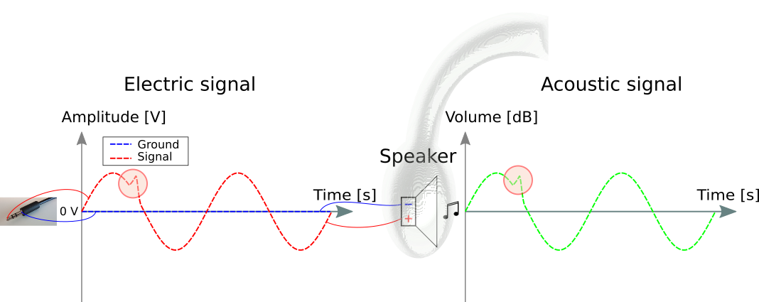
Figure 2. Unbalanced signal with noise. CC-BY-SA.
The electrical noise spike is reproduced as audible noise, which is not very pleasant for the listener. These spikes may have many forms, but you may have encountered them in cars where you may hear engine hum over the speaker system, or at home you may hear a deep constant hum caused by the 50 or 60 Hz frequency present in the electric system. How may this be mitigated? A common and effective solution is a balanced system. In such a setup, three wires are used for a single audio channel (left and right). These are named positive/hot, negative/cold and ground. Balanced systems are almost always used in studios, at concert venues and sometimes at home by Hi-Fi enthusiasts.
In Figure 3, the same noise occurs on the electrical line as in Figure 2:
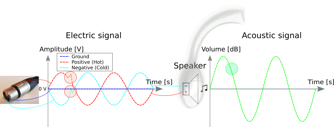
Figure 3. An XLR (three pin plug) connects to an audio source which produces a balanced signal. CC-BY-SA.
The general idea is that electrical spikes will still occur, but a spike will be almost equal in amplitude in both the positive and negative conductor. Since the speaker is now using the voltage difference between the positive and negative conductor, the spike will appear equally on the speaker input, and hence the spike will not be converted into sound. Explained in another way, if the voltage of both the positive and negative conductor is raised by e.g. 5 V with respect to ground, the speaker will never know since it only looks at the voltage difference. The ground is no longer known to the speaker. In other audio equipment the balanced signal may be converted back to unbalanced for further processing. As can be seen in Figure 3, the volume is doubled as an effect of the voltage difference. This effectively doubles the slew rate of the system (the voltage change per unit of time) which may be acoustically beneficial .
The unbalanced->balanced headphones.
I had a pair of headphones which I wanted to convert from unbalanced to balanced.
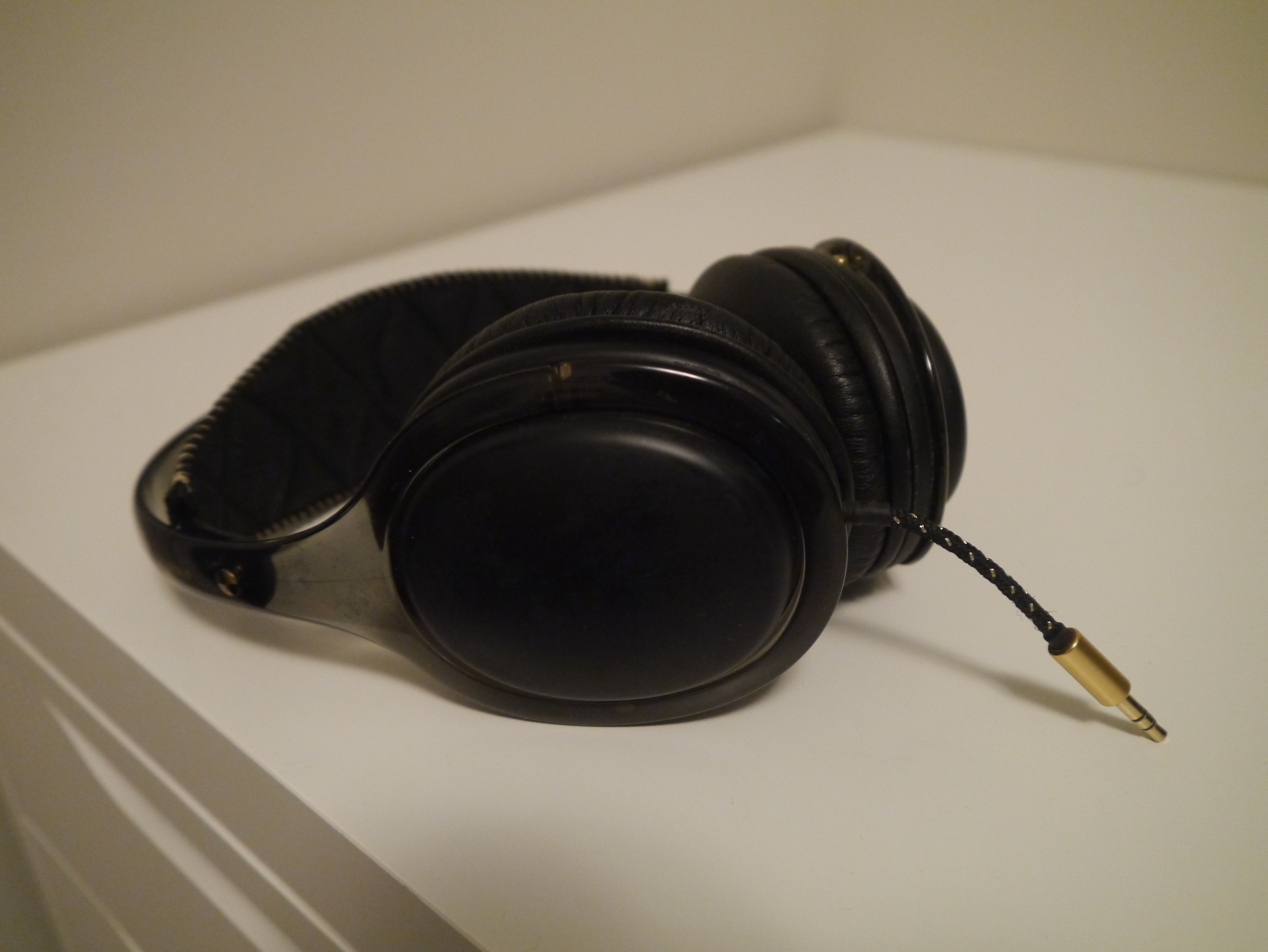
Figure 4. Headphones before alterations.
The process begun by opening the headphones, using a multimeter between the 3.5 mm jack plug and speakers to make sure the polarity was marked correctly.
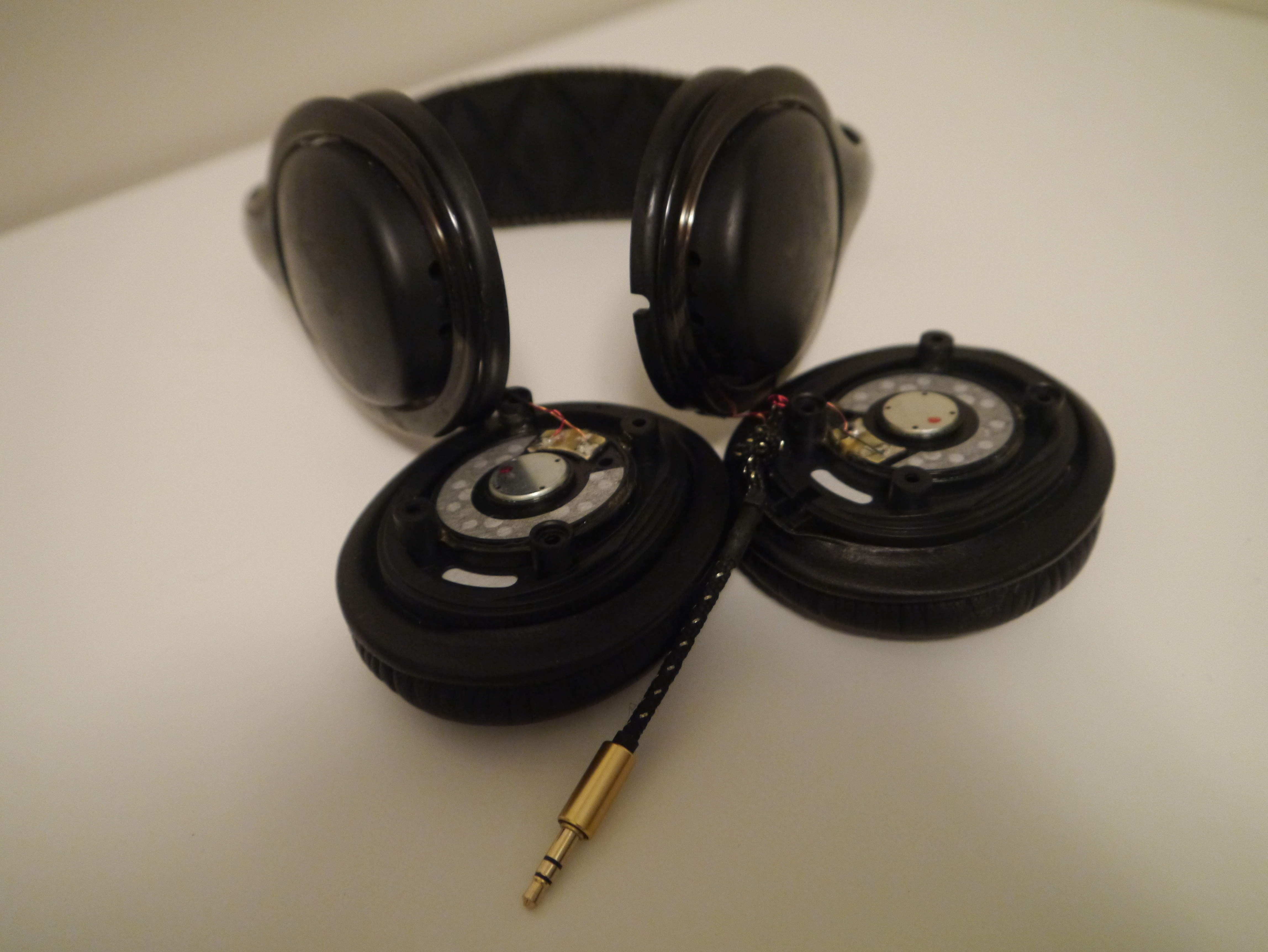
Figure 5. Headphones dismantled.
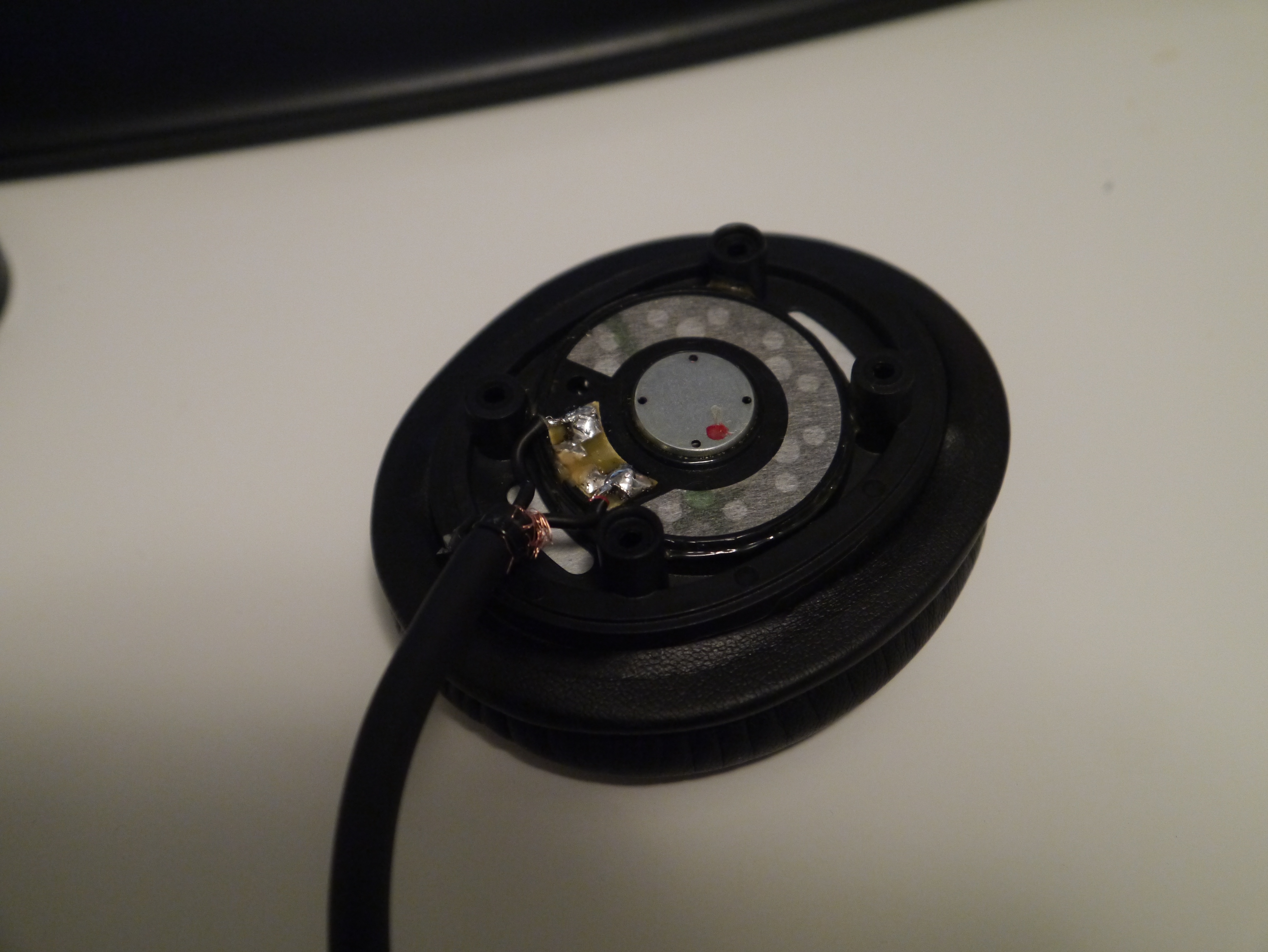
Figure 6. New balanced cabled soldered into place.
The new balanced cable is soldered into place. The red dot on the right hand side marks the position where the positive connection used to be. Solder the new positive conductor of the balanced cable to this point, and attach the negative conductor to where ground was connected before. I did this procedure for both headphones, and used zip tie around the cable before mounting the headphones back together. This latter step ensures that if the cable is pulled cable, no force is put on the solder joints.
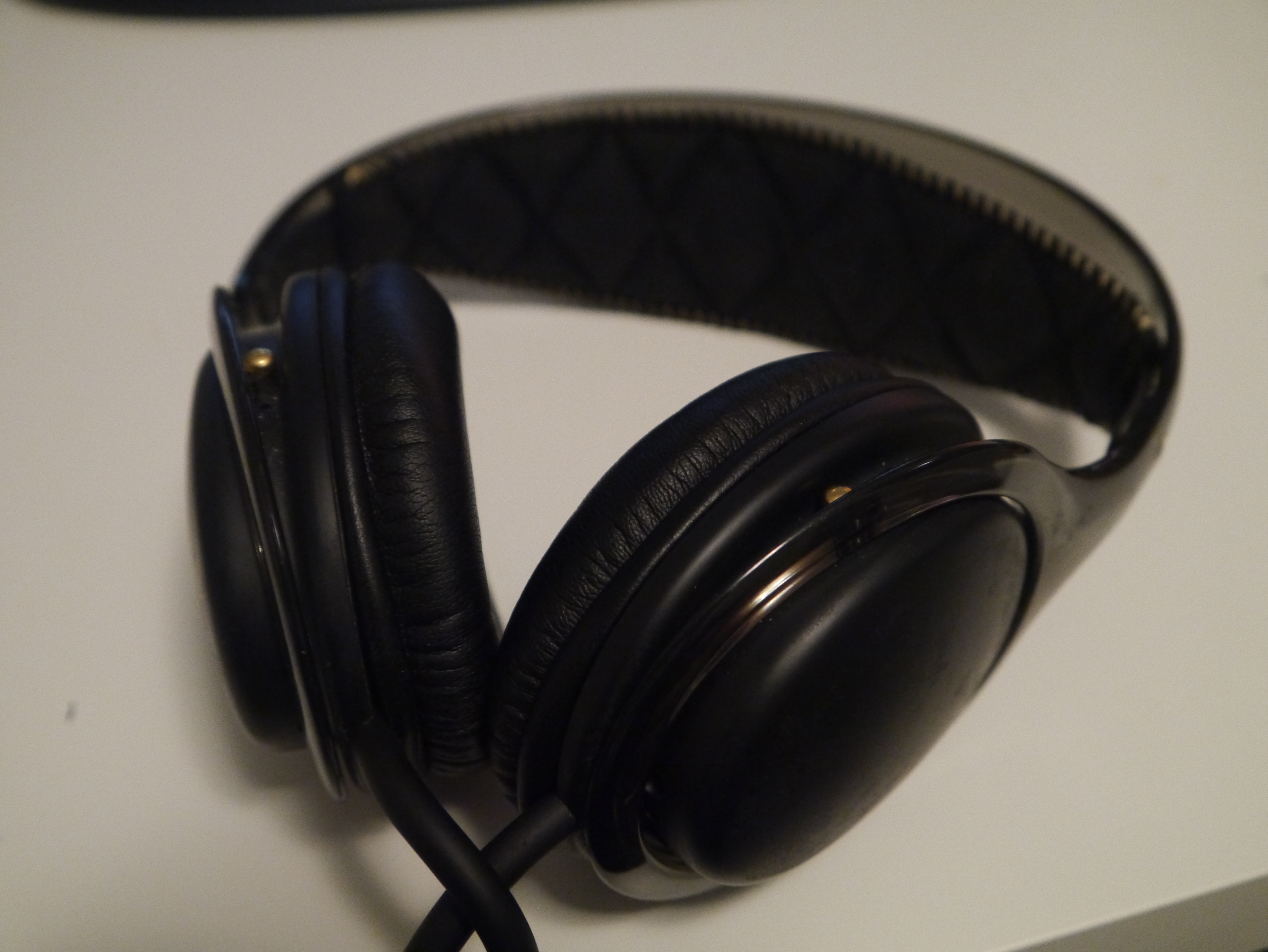
Figure 7. Finished product.
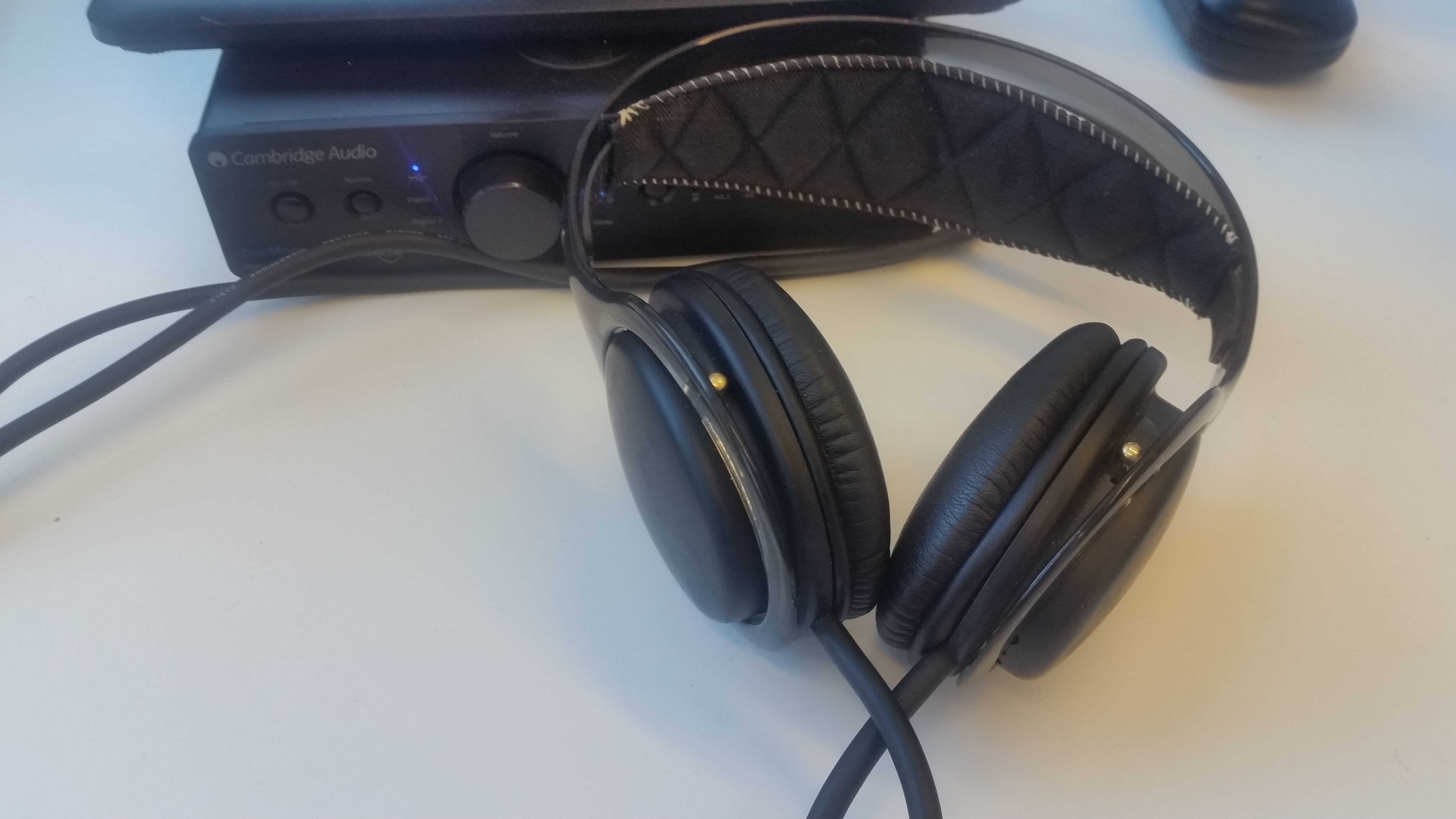
Figure 8. Finished product.
Behold the finished product! A Cambridge Audio DacMagic Plus was used to drive the headphones. The XLR outputs of this or any Digital Analog converter (DAC) for that matter may not be designed to drive low-impedance sinks such as headphones. This may lead to high current consumption and thus unwanted and worst case dangerous results. The XLR outputs are usually meant to connect to high-impedance inputs such as amplifiers or mixers. Though, I have used this setup for several months with no ill-effects.
The results?
I need more time to evaluate the setup, but with such short signal paths as here, there is no audible difference as far as I am concerned. This may be a result of the signal path being too short for any noticeable noise influence to occur, as well as the headphones themselves not being the best to begin with. There is definitely a difference from my previous setup where the internal laptop sound card was used, attributed to the external DAC.