This project begun when a group of friends needed to establish some means of communication between several cars. Naturally, being radio amateurs, we chose to use our hand held radios capable of communicating on the 2 m and 70 cm band. This walkie-talkie setup provides instant free communication independent of any infrastructure such as ordinary mobile networks.
However, as many a car audio enthusiast has witnessed, the alternator in any petrol or diesel car can generate a lot of noise which is dependent on the engine RPM. Unfortunately, this noise tends to be smack in the middle of the audible frequency range as the RPM of a car often ranges from about 800 to 7000. In comparison, the human ear is capable of detecting sounds more or less in the range of 15 Hz to 20 kHz. – Not ideal for car audio or walkie-talkies for that matter.
In response to this I wanted to make a simple low pass filter to be able to charge my walkie-talkie without this adverse effect.
The filter needed to adhere to the following properties:
– Cutoff frequency of 800 Hz, preferably even lower
– Able to supply 1 A of charge current
The design begun by creating the circuit in LTspice http://www.linear.com/designtools/software/#LTspice is a free SPICE (Simulation Program with Integrated Circuit Emphasis) and is ideal for simulating a filter such as this.
Now, there are vast amounts of different filter designs to choose from, and a through explanation of these are beyond the scope of this guide. For this design a second order LC (inductor and capacitor) design was chosen. This is simple design and avoids a series resistor which requires extra caution when used in high current applications such as this due to the voltage drop across the resistor.
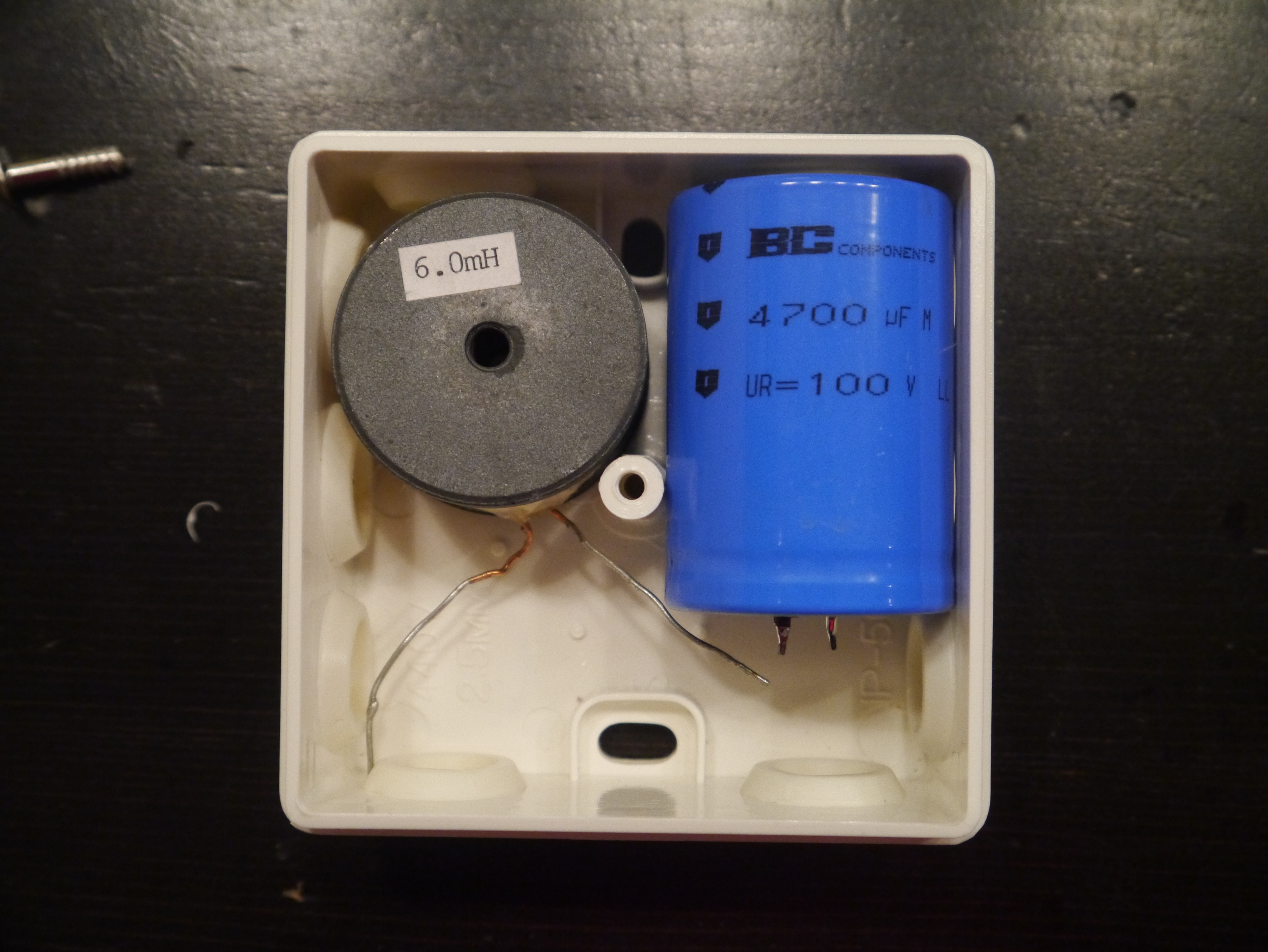
I wanted to use components which I already had available and that would fit into a suitable sized portable box. After some tinkering with the values the following design emerged:

A 6 µH inductor and a 4.7 µF capacitor to ground. R_L is a simulated simplified 12 Ω load resistor to create some current flow in the circuit. The series resistance of L1 was measured and set to 0.6 Ω. The latter value is important as it dictates power dissipation and thus heat generation within the inductor. To simulate the design, choose “Simulate”->”Edit Simulaton Cmd”. The following window appears:
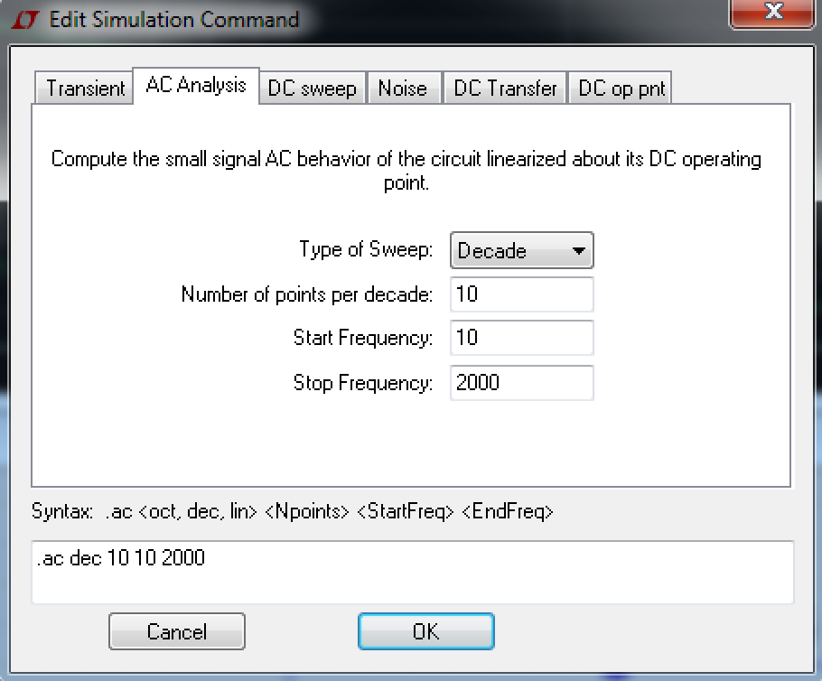
An ordinary decade sweep was chosen, and the start and stop frequency set to 10 Hz and 2 kHz respectively. Press “OK”, and run the simulation. Place the probe marker on the positive side of R_L and the following plot should appear:
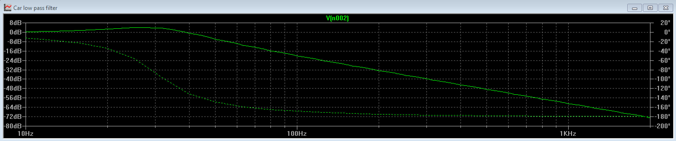
The -3 dB cutoff frequency is at about 45 Hz, in other words at 45 Hz the signal will be dampened by ~50%. As stated, the alternator noise may be as low as 800 Hz, where this filter dampens at -56 dB or 2.5*10^-6! This is overkill but there might be harmonics present at lower frequencies as well, but this is unknown. All in all it is likely that the available components will perform more that adequate. Given a load of 1 A the power dissipation according to Ohm’s law (which applies only in DC) will be (according to U=R*I): 1 A*0.6 Ω = 0.6 V across L1, and (according to P = U*I) 0.6 V * 1 A = 0.6 W dissipated in L1.
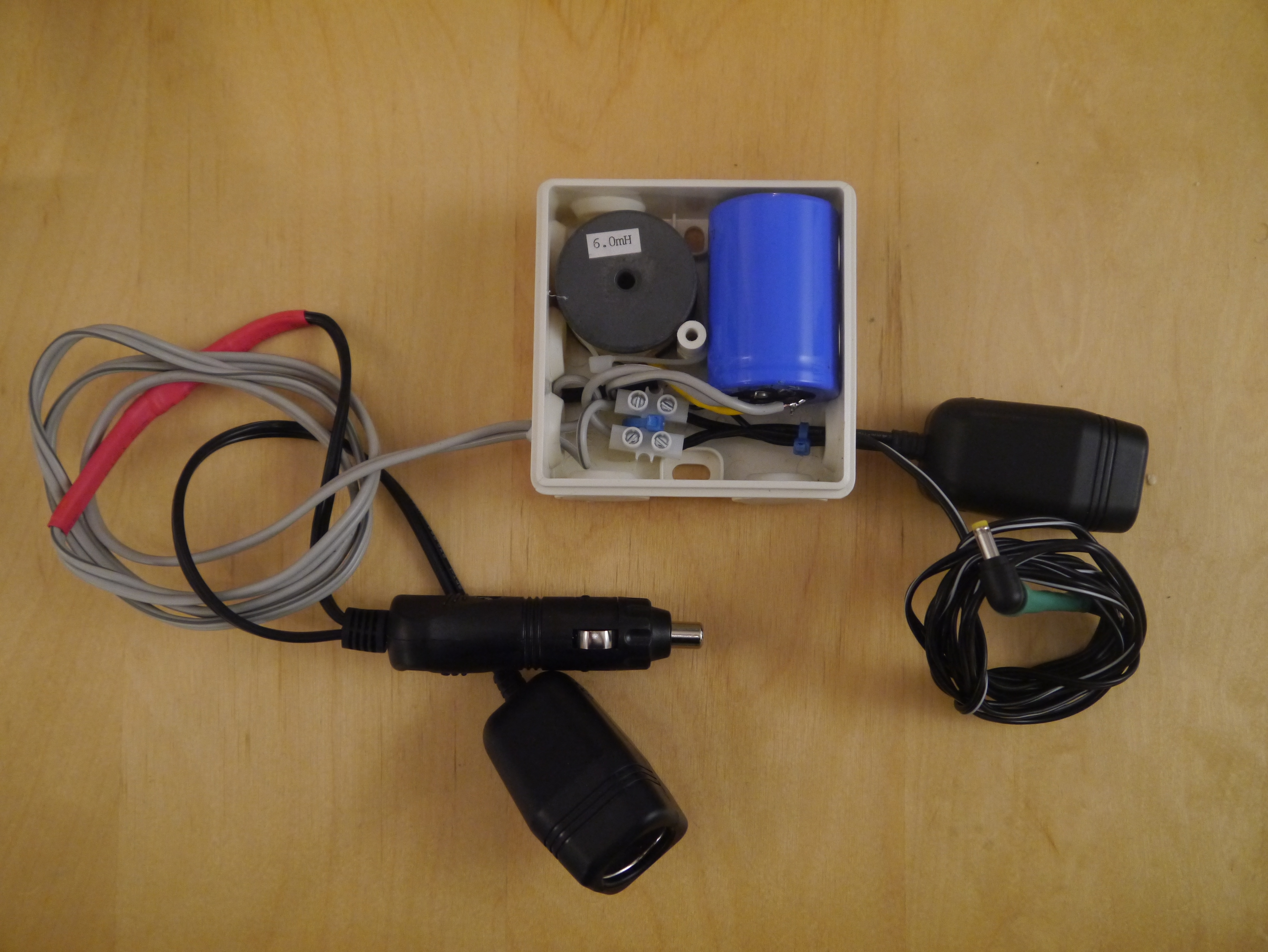
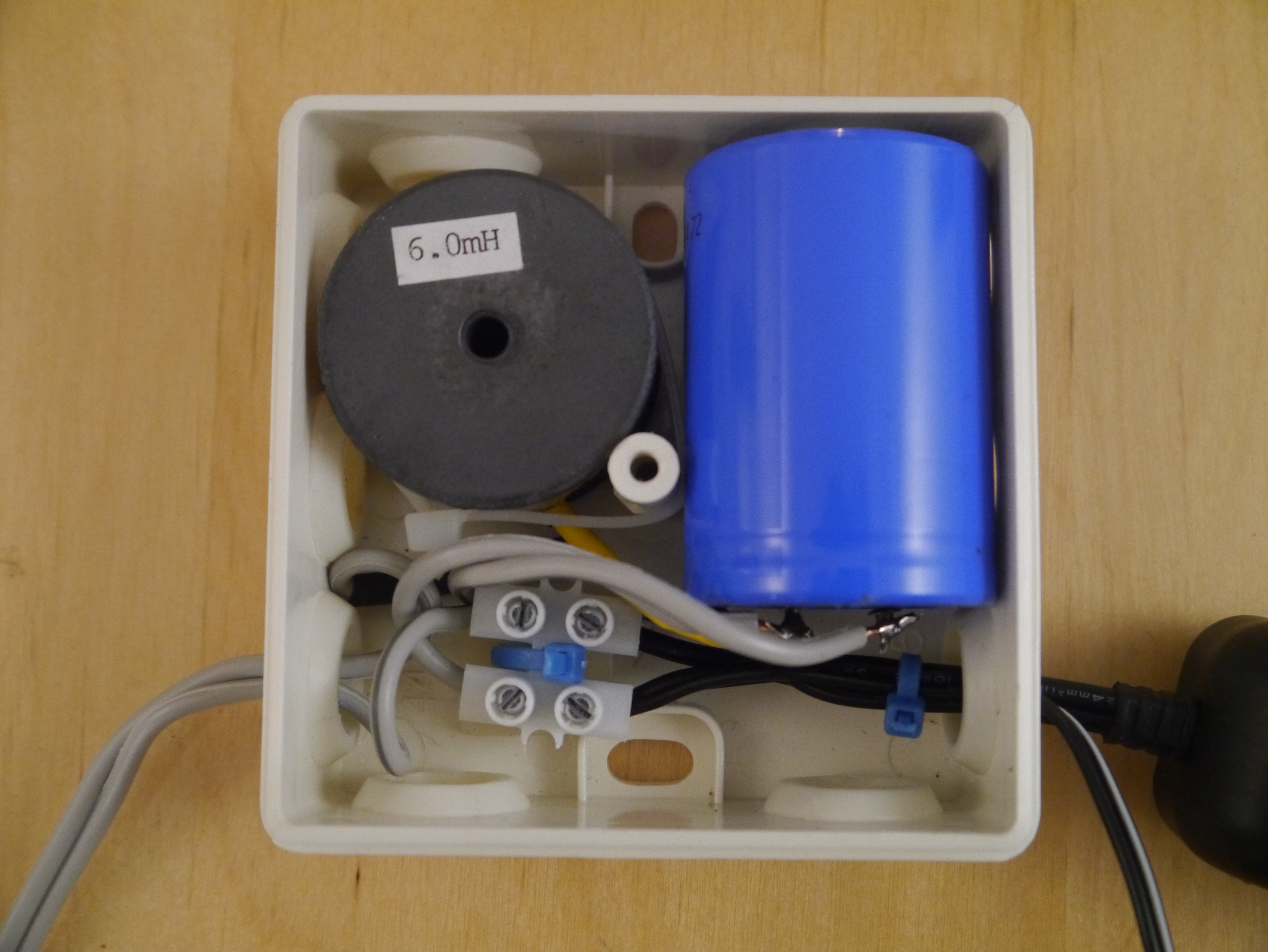
This leads ut to the actual construction of the filter. Components places in the enclosure:
All soldered and wired. Note the cable ties on the wires to prevent stressing of the internal components:
The final product!